1. Navier stokes, Euler or Tabular?
When we talk about modeling the aerodynamic forces and torques, there are basically three main options:
- The first one is to compute the 3D airflow all around the model using the Navier Stokes equations, plus equations of turbulence and integrate the resulting pressure on the model. This is what professionals do when they have to model a real aircraft. Unfortunately, our CPUs are not powerful enough to be able to compute this in real time. This option cannot be envisaged for a PC based simulator.
- The second option is to use a simplified computation around the aircraft. I think that this is the solution used for X plane. This model is very attractive because it is directly linked with the geometry of the aircraft, which means that by defining the global geometric parameters, the model will react accordingly. While attractive I considered that this model was not precise enough, especially for the F-16. Indeed this model is very poor for high AOA, and supersonic areas and that would have been clearly a step back compared to High Fidelity Flight Model (HFFM) data.
- The last option is to use tabular data that represents all the non-dimensional coefficients used to describe the performance of an aircraft. I chose this option mainly because:
- The retro engineering based on real performance of the F-16 was done already (HFFM).
- Exhaustive wind tunnel testing results were available for the F-16.
2. The Development of the Aero Module
The main idea when I started to develop the new flight model engine was to start with Non Fly-By-Wire (NFBW) aircraft to validate the physics engine . Then once was finished, to implement the NASA simulator of the F-16 that was developed at Langley (I didn’t want to validate the physics engine with a non-stable AC at first).
The NASA technical paper was based on the wind tunnel testing of the F-16 and was based on “global computation” of the forces coming from the airflow. That means global forces (static and dynamic) and torques in the 3-axis body system.
While this representation of the forces/torques matrix (we call it a Torsor) is the one generally used in the aero industry/labs, I found it was not very convenient to develop a brand new model with it and I decided to choose for the NFBW aero module a more physical description of the aero forces and torques that I will call: “local computation”.
2.1 The Local Computation – NFBW Aero Code
I think that this way of modeling is probably the most intuitive in terms of physics modeling. It consists of creating tabular data for every local surface of the aircraft (right wing, left wing, right elevator, left elevator, fuselage , TEF, LEF etc.)
The tabular data will contain the lift and drag of each surface of the aircraft vs. AOA and Mach.
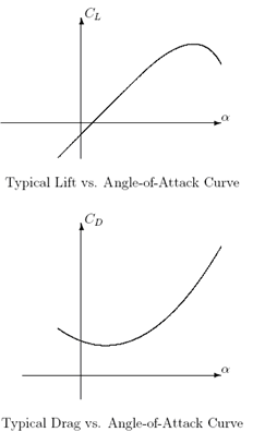
Then the idea is to compute during the motion of the aircraft the local speed and AOA on each surface which will give a local force and torque. By adding all the forces and torques coming from all the surfaces, we get the global forces and torques applied on the aircraft.
This aero module features:
- Main wings
- Elevators : classics (fixed part + tef) or mono bloc
- Rudders : classics (fix part + tef) or mono bloc
- Canards: classics (fix part + tef) or mono bloc
- Fuselage
Additionally some special effects have been developed:
- Fuselage shadowing
- Tail shadowing
- Dihedral effect
I will not enter into all the details of stability problems and influences of the aircraft motions on each surface as this is not the purpose of this document. I chose to expose simply some of the typical aerodynamic / stability problems to give a taste of the complexity that is now part of the new NFBW aero code.
ROLL STABILITY & TURNS
Natural roll stability
Let’s imagine a situation where an aircraft is flying straight with 10 degree of AOA. The pilot engages a roll right with the stick. What happens locally?
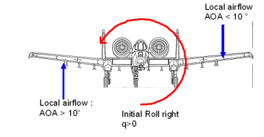
The right wing receives some air coming from below while the left wing receives some air coming from above. Consequently, the right wing will be at >10° AOA while the left wing will be at <10° deg AOA. That means that the right wing creates much more lift than the left wing during the roll.
As an immediate consequence: the main wings are counteracting the initial roll:
- A classic airplane is generally stable in roll because of this natural counter acting effect.
- The roll rate is limited by the same effect.
It’s easy now to see why a spin stall can be triggered during a roll. Indeed, if the aircraft is rolling too fast, the right wing can achieve huge local AOA and enter into a stall. If the right wing stalls there are two phenomenons:
- The natural effect counter acting the roll vanishes and the aircraft increases its roll rate,
- The drag of the stalled wing becomes huge which produces a yawing torque–the aircraft can enter spin stall.
Roll coupling in a turn
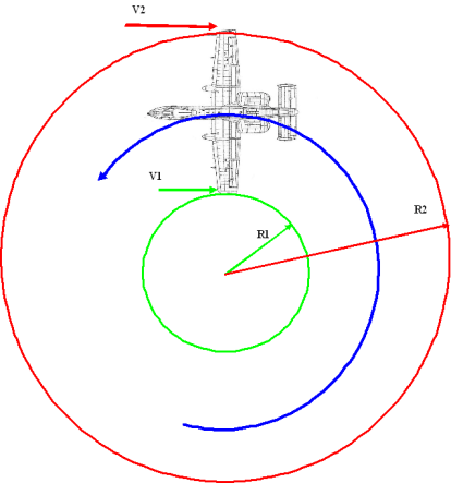
R2 > R1 => V2 > V1 => Lift RW > Lift LW => Roll LEFT
In a turn and without any other interaction (i.e. no side slip) the aircraft has a natural tendency to increase bank angle. To counteract that effect, the pilot has to maintain some slight pressure on the stick opposite to the turn.
YAW STABILITY
Tail
On classic aircraft shapes, the tail is the only vertical surface, therefore has a major role in aircraft yaw stability.
When the aircraft is yawing, let’s say to the left, the tail receives airflow from the right, therefore will develop a lateral lift to the left. The tail has then a natural tendency to counteract any yawing. However, the tail being the only surface to act on that plan, the response to a yaw movement is usually an oscillation (small amortization).
- If the tail is too small, the effect will not be sufficient to counteract the yaw
- If the tail is too big, the response will be too stiff and the tail will inter into oscillations that could eventually lead to another type of instability
As a consequence, designing a proper tail for every flight regimes is extremely difficult; sometimes engineers have added vertical surfaces under the aircraft like the F-14, MiG-23 (and even our F-16) to add some directional stability. The final solution that solves most of the problem of tail has been developed with the Yaw Stability Augmentation System that is an active control of the rudder to reduce oscillations and increase yaw control. (Yaw SAS has been developed as well in BMS and will be detailed in a further developer’s note)
Rudder
The effect of the rudder depends on several parameters and can be very different depending on the shape of the aircraft.
Let’s analyze the different effects. We take as an assumption that the pilot puts the pedal to the right, as a consequence, the rudder is turned to the right.
- As a primary effect, the rudder to the right develops a Lifting force to the left; therefore as the acting point of that force is located at the aero center of the tail, an X torque to the left is generated. The initial response of the aircraft is then a roll to the left,
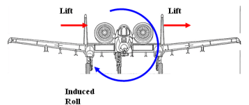
- Then left lifting force naturally generates a yaw to the right in the same time, nose is then pointed to the right,
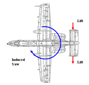
- As a secondary effect, the yaw to the right induces a global side slip to the left, the dihedral effect and the fuselage masking usually provokes a roll to the right (see below)
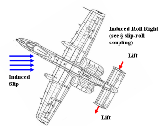
Sometimes, the final rolling effect of the rudder is so important that pilot only use rudder to roll. This is the case on the F-14 at high speed. Indeed the sweep wing angle is so important (similar to dihedral effect) that any side slip coming from rudder input provokes a massive amount of roll …this maneuver is known as “Rudder Roll”.
Tail Shadowing
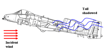
When the AOA of the aircraft is important and the airflow is not laminar anymore, this can create a situation where the tail is within the disturbed airflow coming from the main wings. This decreases the efficiency of the tail and can affect yaw stability.
SLIP – ROLL COUPLING
Dihedral effect
The dihedral effect has always been used to improve the rolling stability of aircraft.
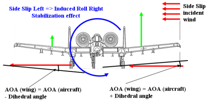
Lift Left Wing > Lift Right Wing
In the situation here above, if the aircraft is entering side slip–let’s say side slip to the left, then as a consequence of the dihedral, the left wing has an apparent AOA higher than the right wing (therefore lift of left wing is higher than right one). The result is that the aircraft will roll right.
In a turn, the natural tendency of an aircraft is to slide on the internal side of the turn (due to gravity), the dihedral effect will then make the aircraft roll to the opposite direction of the turn therefore the aircraft will naturally recover to straight flight.
The dihedral effect is therefore a natural roll stabilization of the aircraft. It has to be noted that the sweep wing angle has a similar effect to dihedral (the more the angle, the more the effect).
The dihedral effect creates a natural coupling between slip and roll.
Fuselage Shadowing
When the aircraft side slip angle is important, the fuselage heavily disturbs the airflow of the wing downstream.
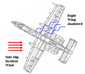
Right wing here receives less air than the other. This creates asymmetrical lift in the situation here above; the aircraft will enter into right roll. The phenomenon can be important and may even triggers wing stalls – spin stall.
CONCLUSION OF NFBW AERO MODULE
All those effects (not all described here) are all acting as in the real world at the same time. Sometimes one effect is counteracting another, sometimes it does not.
However the interest of all of this is not to identify each “effect” individually, but more mixing all those physical effects to make the aircraft feel like a real one.
In conclusion, I am extremely satisfied to have coded the causes rather than the effects. The result is exactly what I was expecting — total renewal of the feeling of flight in Falcon 4.
2.2 The Global Computation – F-16 Aero Code
The F-16 flight model’s core developed for BMS (AFM) is mainly based on the NASA simulator developed at Langley in 1979.
The Source can be found at NASA resource center (or clicking below):
Nasa Technical Paper 1538 ( TP 1538 )
“Simulator Study of Stall / Post Sall Characteristics of a Fighter Airplane with Relaxed Longitudinal Static Stability”
2.2.1 The Aerodynamic Data
The aerodynamic data used in this NASA simulation were derived from low-speed wing static and dynamic (force oscillation) wind-tunnel tests of sub-scale models of the F-16 in wind-tunnel facilities at the NASA Ames and Langley research Centers.
There are 6 “global” aerodynamic coefficients to completely describe a model:
The Forces:
- CL : Lift Coefficient (reference airflow)
- CD : Drag Coefficient (reference airflow)
- CY : Y-Axis Force Coefficient (reference body)
The Moments:
- Cm : pitching moment
- Cn : yawing moment
- Cl : rolling moment
The NASA performed wind tunnel testing to evaluate all those parameters in a maximum of possible conditions (static and dynamic). However those testing have been performed at mach 0.6 equivalents–which would have been totally insufficient for our model dedicated to fly in the whole flight envelope.
Thankfully, HFFM data were retro engineered from real performance charts, which means HFFM data included CL and CD for the whole flight envelope (mach 0 to mach 2.2).
For the moments coefficients, no other data other than mach 0.6 wind tunnel testing were available. However, because of the FLCS, the pitch/roll/yaw behavior is fully controlled artificially across the whole flight envelope. We can say that using mach 0.6 moments coefficient for the whole flight envelope will not make the flight model deviate from the real too much. Indeed, from mach 0 to mach 0.9, the moments coefficient do not evolve that much and above mach 0.9, it is clear that the model evolves in a very low AOA envelope and therefore the pitching/rolling/yawing reactions of the model are much governed via the FLCS than from the pure aerodynamics coefficient.
Finally it has been chosen to use:
- HFFM data for CL/CD (and Thrust)
- NASA data for all other coefficients.
The association of HFFM and NASA data certainly ensures a very high level of F-16 simulation accuracy through the whole flight envelope.
2.2.2 Dependence of Aerodynamic Data
It will be useless to write here all the equations governing the dependencies of the different coefficients with parameters. However to give you a taste of the dynamic and coupling included in the model, hereafter is a chart that summarizes those dependencies. All data included in the NASA Technical paper have been included in the AFM, therefore the AFM includes all those dependencies; it represents several thousands of coefficients. All those dependencies here will make the “aircraft on rails” feeling like a very old, bad nightmare.
List of Variables:
α = Angle of Attack
β = Side Slip Angle
p = Roll rate
q = Pitch rate
r = yaw rate
δsb = Speed Brake deflection
δlef = Leading Edge flap deflection
δh = Elevator deflection
δr = Rudder deflection
δa = Aileron deflection
ds = deep stall
| Aero Coefficient | Variable Dependence |
| CL / CD | Retro Engineered |
| CY | α, β, r, p, δa, δlef, δr |
| Cm | α, β, q, δh, δlef, δsb, ds |
| Cl | α, β, r, p, δh, δa, δr, δlef |
| Cn | α, β, r, p, δh, δa, δr, δlef |
Special thanks to all the BMS members that have been involved in the laborious copying of those coefficients.

