1. Introduction
The main -so called- mechanical parameters that impact on the physical model are:
- The Mass and the position of the Center of Gravity (CG) (or Gravity Center – GC)
- The Inertia Matrix
Basically and without entering too much into mathematics, the mass is the parameter that influences the trajectory of the CG while the inertia matrix influences the rotations of the solid.
The inertia matrix is the equivalent of the mass for the rotation motions. It says how difficult it is to make the object rotate around one axis and it also governs the coupling of the different rotation axis, for instance, turning an object around the X axis could influence its turning on the Y axis as well. The inertia matrix is dependent on the repartition of the mass within the object.
While the original Falcon 4.0 flight model takes the mass into account, it did not take into account the inertia matrix, simply because as explained in the first FM developer’s note, the original Falcon 4.0 flight model does not apply physics to the rotation motions.
The main purpose of the Mechanical module is to compute in real time all those parameters and feed the Equations of Motion module.
2. The Mass and Gravity Center position
In the new flight model, the mass is constantly updated taking into account:
- Empty mass
- Fuel mass
- Weapons mass
What is new here is that the module is also updating the position of the CG.
The position of the gravity moves:
- Along the X axis, it determines the stability in pitch of the aircraft
- Along the Y axis, it determines the trim conditions in roll.
The position of the CG along the X axis is extremely critical for the F-16 because the empty CG position is already AFT, making the aircraft instable. The FLCS is able to manage this negative static margin, however within certain limits.
The FLCS has been designed for a center of gravity at 0.35c (35%MAC), c being the main chord of the wing (11.32ft).
It is important to understand that during a mission, the CG position evolves with fuel consumption and loadout delivery. Basically the engineers have positioned and calculated the fuel tank position and fuel management system in order to stay within the limits of the FLCS. The positions of the pylons have been determined accordingly. However, it is the responsibility of the pilot to ensure that the CG will stay within limits all along the flight with the chosen loadout.
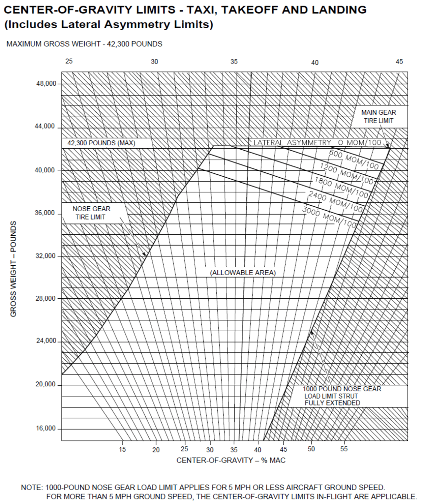
Here is a figure showing the allowed limits of CG displacement in %MAC. You can see here that the FLCS is quite resistant to CG displacement. Pay attention to the asymmetry problem as well for heavy weights.

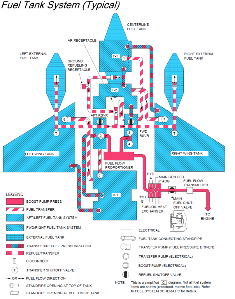
A complete, new fuel management system has been developed. Each fuel tank position has been included in the model, a new fuel tank has been included (F-2) that did not exist in Falcon 4.0 (previous versions of Falcon had combined the F-1 and F-2 tanks) and the external fuel tanks have been divided into three compartments as in the real aircraft with the real fuel transition from one compartment to the other.
Note that the fuel selector FWD/AFT is now really acting on the balance of the aircraft and plays on the position of the CG along the Y axis. It could theoretically be used to “trim” the AC in roll. You might be wondering “I thought we were talking about forward and aft, how can that affect roll?” Recall that the fuel tank system is a two-part system consisting of Forward-Right and Aft-Left tank components. The forward reservoir is on the right side of the fuselage body, while the aft reservoir is on the left side of the fuselage body, thus affecting roll left/right. Here is a schematic of the fuel tank system, note the F-2 tank that is now included in BMS.

The slots under the wings or body have been modified to correspond accurately to the real aircraft and the whole weapon database has been modified to correctly reposition the weapons and their affect on CG.
Finally, BMS now accurately simulates the variation of the CG position in real time, taking into account fuel and weapons. For the pilot, it means that the reactivity of the aircraft and the risk of departure is now dependent on fuel and the loadout.
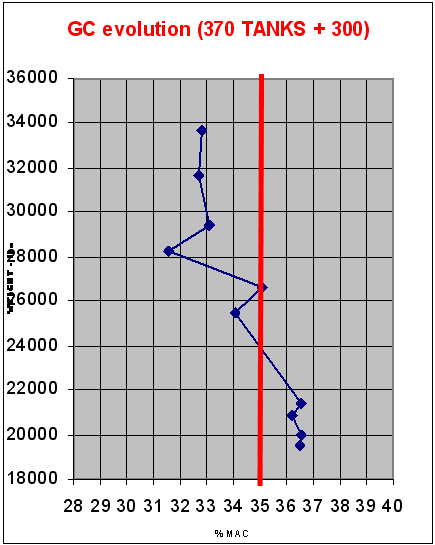
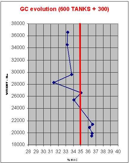
Here is typical CG evolution with fuel consumption.
From those figures, we can see that at the beginning of the mission, with a full fuel load, the aircraft is more stable. CG position evolves around 33%MAC which means it is less responsive in pitch.
However at the end of the mission, when fuel is low, the CG is at 36.5% MAC, which means very aft. In that case, the aircraft will be very responsive in pitch (higher pitch rates are attainable) but susceptibility to departures and deep stalls increase (especially since you may likely be in a CAT1 configuration where there are less limitations in roll rates and essentially greater pitch authority). The most aft CG occurs with approximately 2000 lbs of internal fuel remaining in the C model. In the D model, the most aft CG occurs when the external fuel tanks have just emptied. This is due to a smaller F-1 fuselage tank since there is an additional cockpit for the backseat pilot.
3. The Inertia Matrix
Poor attempts to implement inertia of the weapons have been made in the past years. Basically those attempts where hacked on the roll response of the aircraft. BMS now models and updates in real time the inertia matrix of the aircraft taking into account fuel consumption and weapons.
Be ready to feel less response in roll when you carry heavy weapons or full fuel in the wings.


